Product Overview
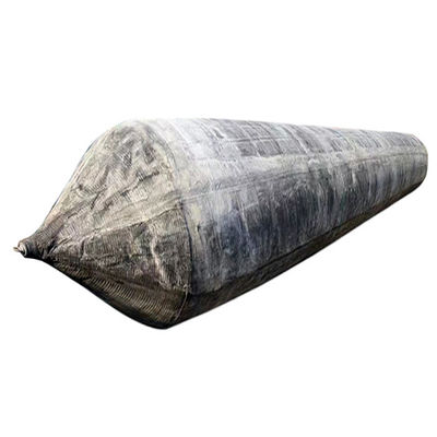
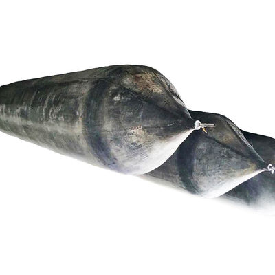
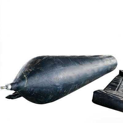
The product typically incorporates a multilayer rubber structure reinforced with high-strength synthetic cord fabric. The rubber compound forms the flexible outer membrane and air-retaining body, while the reinforcement layers provide tensile resistance and help control expansion under internal pressure. The structural arrangement must accommodate repeated inflation, loading, rolling contact, unloading, and deflation without unacceptable deterioration. The rubber formulation, reinforcement material, layer configuration, bonding method, and end construction should be selected according to the intended operating pressure, loading conditions, environmental exposure, and expected service requirements. Exact construction details depend on the approved product specification.
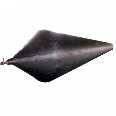
Unlike a rigid launching support, a Ship Launching Balloon changes its contact geometry as external forces are applied. The cylindrical body becomes locally flattened beneath the vessel and against the supporting surface, creating a contact area through which the applied load is transferred. The resulting support force is influenced by internal pressure, balloon diameter, effective length, deformation, membrane properties, and the characteristics of the ground. Consequently, the engineering capacity of the system cannot be determined from the inflation pressure or nominal dimensions alone. The design must establish an acceptable relationship between applied load, contact area, allowable deformation, and structural stress.
The system can be supplied in different diameters, lengths, reinforcement configurations, and fitting arrangements to accommodate project requirements. Diameter affects the available clearance beneath the hull and the deformation profile under loading, while effective length influences the contact area and the distribution of supporting force. The required number of balloons and their longitudinal spacing depend on vessel weight, center-of-gravity location, hull geometry, bottom framing, ground bearing capacity, and the planned launching procedure. For vessels with substantial differences in weight distribution or hull structure, the support layout should be assessed individually rather than copied from an unrelated project.
Operational stability depends on the interaction between the balloon arrangement and the launching surface. A uniform, adequately bearing surface helps maintain predictable contact and reduces the likelihood of localized settlement. Conversely, soft ground, abrupt changes in elevation, surface depressions, or sharp debris may cause uneven deformation, damage, or changes in vessel alignment. The launching route should therefore be surveyed and prepared before installation. Where the route includes an incline or a transition to water, the engineering plan must address vessel restraint, movement control, changing support conditions, and the effects of progressive buoyancy.
The rubber structure must also withstand the environmental conditions associated with shipyard operations. Exposure to moisture, sunlight, temperature variation, and routine abrasion should be considered when selecting materials and defining maintenance requirements. Contact with oils, solvents, sharp metal edges, or other incompatible substances may adversely affect the rubber compound. Environmental adaptability therefore depends on selecting appropriate materials and protecting the product from conditions outside its specified operating limits.
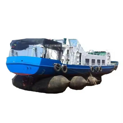
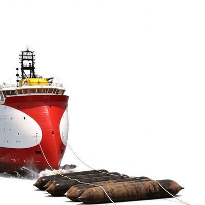
During a launching operation, the balloons are placed at designated positions beneath the vessel, inspected, and inflated in accordance with the approved procedure. The vessel is transferred progressively onto the support arrangement, after which movement is controlled while the balloons rotate along the prepared surface. Operators monitor pressure, deformation, alignment, and the behavior of the supporting ground throughout the process. If abnormal deformation, unexpected settlement, pressure loss, or uncontrolled movement occurs, the operation must be stopped and the condition assessed before work resumes.
Ship Launching Balloon can support suitable fishing vessels, cargo vessels, barges, workboats, and other marine structures when the hull geometry, loading conditions, and site characteristics are compatible with the system. Its engineering value lies in providing reusable inflatable support that can be configured for a defined launching task. Depending on the project, this may reduce dependence on certain permanent launching arrangements and improve the flexibility of shipyard space utilization. However, the product does not eliminate the need for engineering calculations, ground preparation, structural compatibility checks, trained personnel, or an approved movement-control plan.
After use, each balloon should be inspected for cuts, punctures, unusual bulging, surface deterioration, exposed reinforcement, damaged fittings, and other indications of reduced structural integrity. Serviceable units may be cleaned, deflated, and stored under the manufacturer's recommended conditions. Units with unexplained pressure loss or suspected reinforcement damage should be isolated pending competent technical assessment. A documented inspection and maintenance system helps shipyards manage repeated use, track product condition, and reduce the risk of returning unsuitable equipment to service.
Illustrative Case Study: Shipyard Launching Project in Northern Vietnam
A medium-sized shipbuilding contractor in northern Vietnam is assumed to be preparing to launch a steel-hulled harbor service vessel with an estimated launching weight of 380 tonnes. The vessel is designed for maintenance work, equipment transport, and operational support within commercial ports and coastal industrial zones. The shipyard's production area has limited room for permanent launching installations because the same land is used for hull assembly, machinery installation, temporary storage, and the preparation of subsequent vessels. These project details are illustrative and are not a verified customer installation or documented Hongruntong Marine project.
The operational challenge is to move the completed vessel from its assembly position to a designated water-entry point while maintaining stable support beneath the hull. The vessel has a different bottom arrangement and weight distribution from other craft previously handled at the site, making it inappropriate to rely solely on an existing support layout. The shipyard must also account for a relatively narrow launching route, variable ground conditions following periods of rainfall, and the need to coordinate launching activities with other work taking place nearby.
The engineering team first reviews the vessel's principal dimensions, launching weight, center-of-gravity information, hull drawings, and structural support locations. A site survey is conducted to examine the launching path, surface condition, slope, drainage, and ground bearing capacity. The results are used to determine whether an inflatable launching system is appropriate and to identify the site improvements required before the operation. Particular attention is given to areas where water accumulation or uneven ground could cause differential settlement beneath the balloon arrangement.
The proposed Ship Launching Balloon configuration is developed around the vessel's load distribution and available support locations. Balloon dimensions, quantity, spacing, operating pressure, and allowable deformation are evaluated as an integrated system. The engineering review also considers the structural compatibility of the balloon contact areas with the vessel's bottom framing and the forces expected during movement. The final arrangement is accepted only after the relevant loading assumptions and ground conditions have been reviewed by the responsible project personnel.
Before launching, the shipyard clears the route of sharp debris, addresses unsuitable surface irregularities, and verifies that the ground can support the anticipated loads. The balloons are inspected for surface damage and fitting defects, and the inflation equipment is checked. The launching supervisor confirms the support positions, pressure limits, restraint arrangement, movement-control procedure, and communication responsibilities of the operating team. The work area is restricted to authorized personnel, with hazardous zones identified before the vessel is transferred onto the balloons.
During implementation, the balloons are positioned and inflated according to the approved procedure. The vessel is moved progressively, with personnel monitoring alignment, deformation, pressure behavior, and ground response. The narrow launching route requires particular attention to the relative positions of the hull and support units, since lateral displacement could affect the distribution of forces. Movement is maintained within the established control procedure, and the operation is suspended if the vessel shifts unexpectedly, the ground settles, or a balloon shows abnormal deformation.
Following the vessel's successful entry into the water, the launching team recovers and inspects the balloons. The inspection covers the external rubber surface, end closures, valves, and other pressure-retaining components. The team records the operating conditions, identifies any units requiring maintenance, and stores the serviceable balloons in accordance with the manufacturer's instructions. These records establish a reference for later launching operations and help identify whether changes to handling practices or ground preparation are necessary.
The expected operational benefit is greater flexibility in arranging the launching area without committing to extensive permanent infrastructure for this particular vessel movement. Reuse may also support more economical equipment management across subsequent suitable projects. Nevertheless, any reduction in labor, time, or cost would need to be demonstrated using actual project records, including preparation, handling, maintenance, and equipment utilization. A later vessel with a different weight or hull arrangement would require a new assessment before the same configuration could be reused.
The case illustrates the importance of treating Ship Launching Balloon as one component of a complete launching system. Equipment selection, ground engineering, hull compatibility, movement control, and post-operation inspection must be coordinated to support repeatable operations. By documenting the configuration and operational observations, the shipyard can improve its planning process for future projects while maintaining clear acceptance criteria for the equipment.
Key Features
Optimized Reinforcement Architecture for Repeated Mechanical Loading
The structural performance of Ship Launching Balloon depends on the combined behavior of the rubber membrane and the embedded reinforcement layers under internal pressure and external loading. The rubber body provides flexibility and forms the pressure-retaining enclosure, while the reinforcement contributes tensile strength and controls expansion when the balloon supports a vessel. This composite construction is intended to maintain structural continuity as the cylindrical body changes shape under load, rotates along the launching surface, and returns toward its original profile after unloading.
The reinforcement architecture must be compatible with the intended diameter, effective length, working pressure, and operating environment. High-strength synthetic cord reinforcement can provide tensile resistance while allowing the flexibility required for rolling movement. The orientation, spacing, and bonding of the reinforcement layers influence dimensional stability and the distribution of stresses throughout the balloon body. If the construction is not appropriately matched to the operating conditions, repeated deformation may accelerate fatigue, increase local stress, or compromise the integrity of the pressure-retaining structure.
Mechanical loading is not distributed uniformly throughout the balloon. The contact zones beneath the hull and against the ground experience deformation, while other portions of the cylindrical body remain less compressed. The design must account for these differences and ensure that the rubber membrane and reinforcement remain within their specified operating limits. Product evaluation should therefore consider the relationship between internal pressure, contact geometry, applied load, and allowable deformation instead of relying on material strength values alone.
Manufacturing controls are equally important to reinforcement performance. Material preparation, layer positioning, bonding conditions, and end construction must be managed to maintain consistency across the finished product. Particular attention should be given to transitions between the reinforced body and end closures, as well as to the installation of inflation fittings. Inspection of these areas helps identify manufacturing irregularities that may affect pressure retention or mechanical reliability. For shipyards requiring repeated launching operations, an appropriately engineered reinforcement structure provides a foundation for predictable equipment behavior when supported by correct operating practices and maintenance.
Controlled Rolling Mechanics and Reduction of Sliding Resistance
Ship Launching Balloon supports vessel movement through a rolling mechanism rather than relying exclusively on sliding contact between the vessel-support system and the launching surface. When the balloon is positioned beneath the hull and inflated to the specified pressure, the applied load produces a flattened contact region. As the vessel advances, the balloon rotates along the ground, allowing the contact region to move around the cylindrical body while maintaining support beneath the vessel.
The resistance encountered during movement depends on several interacting variables, including the ground surface, balloon deformation, internal pressure, applied load, alignment, and launching slope. A suitably prepared surface can help reduce irregular contact and support more consistent rolling behavior. However, rolling resistance cannot be assumed to be negligible, and it may increase where the ground is soft, uneven, contaminated, or insufficiently compacted. The launching route must therefore be evaluated according to the expected loads and the characteristics of the supporting surface.
The rotational behavior of the balloon also requires coordination between the support arrangement and the vessel's movement-control system. Uneven positioning, inconsistent deformation, or changes in ground elevation may cause differences in the way individual balloons rotate. These differences can affect the vessel's alignment and the load carried by adjacent units. Proper spacing, controlled movement, and continuous observation are therefore necessary to maintain the intended operating geometry.
During the transition toward water, the supporting conditions change as buoyancy progressively contributes to carrying the vessel's weight. This transition must be addressed in the launching plan because the distribution of forces between the hull, balloons, ground, and water changes throughout the operation. Appropriate restraint and movement-control arrangements are required to prevent uncontrolled acceleration or displacement.
The engineering value of the rolling mechanism lies in providing a practical means of moving suitable vessels across prepared surfaces without depending entirely on fixed sliding infrastructure. It can support flexible launching arrangements and improve the utilization of available shipyard space. These benefits remain dependent on proper engineering, suitable ground conditions, and coordinated operating procedures rather than on the rolling action alone.
Load Distribution and Compatibility with Hull Structure
The load-bearing arrangement of Ship Launching Balloon must be designed around the vessel's actual structural configuration. Vessel weight is transferred through the hull into the supporting balloons and then into the ground. The distribution of this load depends on the vessel's center of gravity, longitudinal weight profile, bottom framing, balloon dimensions, support spacing, and deformation characteristics. A suitable configuration must therefore address both the overall vessel load and the local forces applied at individual support locations.
Hull compatibility is particularly important for vessels with different bottom structures. Structural frames, girders, plate thicknesses, and local reinforcements influence the way the hull transfers external forces. If balloon positions do not correspond appropriately to the vessel's support requirements, concentrated loads may develop in areas that are not intended to carry them. The engineering review should identify appropriate support zones and evaluate whether the proposed arrangement maintains acceptable hull stresses during the launching sequence.
The ground forms the other principal part of the load path. Each balloon transfers force to the supporting surface through its effective contact area. If the ground has inadequate bearing capacity or experiences uneven settlement, the balloon may deform differently from adjacent units. This can change the support distribution and create alignment problems. Ground assessment should therefore include surface condition, local bearing capacity, drainage, gradient, and any changes in elevation along the route.
As the vessel advances, the load distribution changes with the position of the hull and the number of balloons actively supporting it. The launching plan should consider the progression of support forces and the transition to buoyancy. Where the vessel is large, the loading arrangement is complex, or uncertainty remains about the hull structure, detailed engineering calculations or structural analysis may be necessary.
A properly evaluated support arrangement helps reduce the likelihood of excessive local loading and uncontrolled deformation. It also establishes a clear basis for determining balloon quantity, spacing, and operating conditions. For shipyards, this feature is important because reliable launching depends on compatibility between the product, the vessel structure, and the ground, rather than on the rated characteristics of an individual balloon in isolation.
Dimensional Customization and Integration with Shipyard Procedures
Ship Launching Balloon can be specified in different diameters, effective lengths, and construction configurations to suit the requirements of a particular launching project. Dimensional selection influences hull clearance, contact geometry, allowable deformation, handling arrangements, and the distribution of support forces. Because these factors interact, the selected configuration must be evaluated as part of the overall launching system rather than chosen solely on the basis of nominal size.
The customization process should begin with reliable vessel and site information. Relevant parameters include launching weight, principal dimensions, hull drawings, weight distribution, bottom framing, support locations, ground conditions, and launching slope. The responsible engineering team can use these data to determine the required balloon quantity, spacing, working pressure, and allowable deformation. If the vessel's loading condition or site geometry changes, the configuration should be reviewed before the equipment is reassigned.
Customization may also involve inflation fittings, valve arrangements, product identification, and handling requirements. Compatibility between the supplied fittings and the shipyard's inflation equipment is important for efficient preparation and maintenance. Clear identification of dimensions and operating limits helps prevent confusion when several balloon types are stored at the same facility. Product documentation should correspond to the actual supplied configuration and specify the applicable operating conditions.
For shipyards handling different vessel classes, this approach can provide flexibility in equipment planning. A set of reusable balloons may be considered for multiple projects when each proposed arrangement is independently assessed and the units remain in acceptable condition. Such reuse does not mean that the same balloon quantity, spacing, or pressure can be applied to every vessel.
The engineering value of customization is that it creates a defined relationship between the product specification and the intended application. This supports procurement accuracy, manufacturing coordination, inspection planning, and future maintenance. By establishing technical requirements before production, the supplier and customer can reduce specification ambiguity and provide a more consistent basis for evaluating product suitability.
Pressure Integrity, Inspection, and Service-Life Management
Pressure integrity is essential to Ship Launching Balloon because the internal air pressure maintains the intended operating profile and contributes to the balloon's load-bearing behavior. The rubber membrane, reinforcement layers, end closures, valves, and inflation fittings must work together to retain pressure under the specified operating conditions. Damage or deterioration in any of these components can affect the product's ability to maintain its intended shape and support characteristics.
The operating pressure must be established according to the manufacturer's specification and the project-specific loading arrangement. Underinflation can cause excessive deformation or insufficient clearance, while overinflation may increase stresses in the membrane and reinforcement. Pressure should not be adjusted arbitrarily to compensate for an unsuitable balloon size, uneven ground, or incorrect load distribution. Operators should follow the approved inflation procedure and use suitable pressure-measuring equipment.
Inspection should be performed before use, during the operation where required by the procedure, and after recovery. Checks should cover cuts, punctures, abnormal bulging, surface separation, exposed reinforcement, fitting damage, valve condition, and unexplained pressure loss. Any sign of structural deterioration should be assessed before the unit is returned to service. Repairs must follow an approved procedure compatible with the actual construction, particularly where the reinforcement or pressure-retaining structure may be affected.
Service-life management also depends on handling and storage. After use, the balloon should be cleaned as appropriate, deflated according to the manufacturer's instructions, and protected from sharp objects, excessive heat, incompatible chemicals, and damaging compression. Storage conditions should limit avoidable environmental deterioration and preserve the integrity of the rubber body and fittings.
Maintenance records can include product identification, inspection dates, operating conditions, pressure observations, repairs, and decisions about continued service. These records help the shipyard identify recurring damage, improve handling procedures, and maintain traceability across multiple launching cycles. Actual service life depends on construction, frequency of use, operating conditions, maintenance, and storage, so it should not be represented by a fixed period without supporting product data.


 Your message must be between 20-3,000 characters!