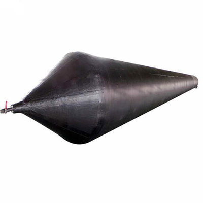
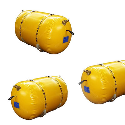
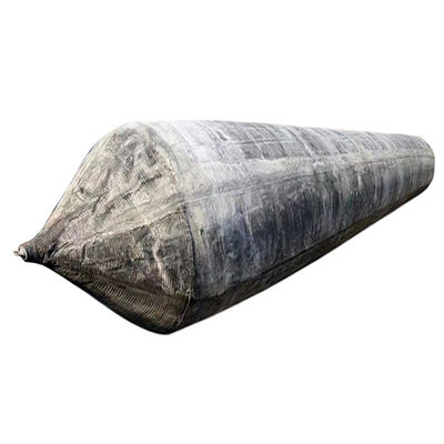
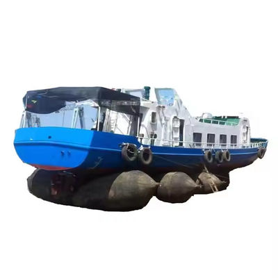
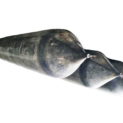
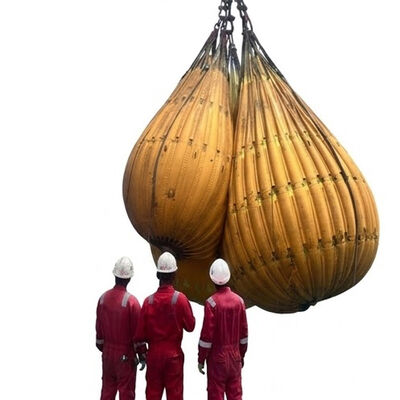
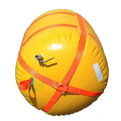
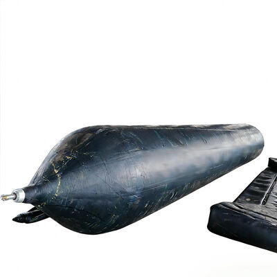
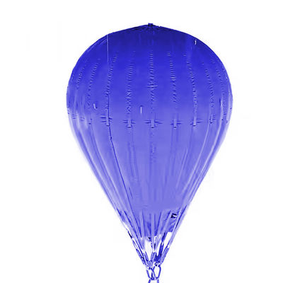
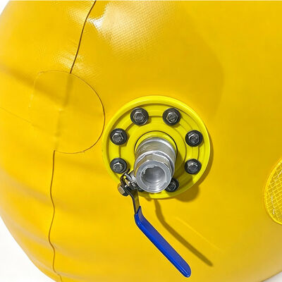
Underwater Lift Bags are flexible buoyancy lifting systems engineered for controlled handling, raising, stabilization, and positioning of submerged loads in marine and industrial environments. The equipment uses enclosed air volume to generate positive buoyancy, reducing the effective submerged weight of a structure or component and allowing operators to control vertical movement without depending entirely on rigid lifting equipment.
The system is suitable for underwater construction, marine maintenance, equipment recovery, pipeline installation, harbor engineering, offshore operations, and other applications where conventional lifting access is restricted.
A marine engineering contractor at a shipyard in Southern Europe successfully recovered and repositioned a submerged steel fabrication module weighing approximately 32 tonnes. The module had settled unevenly on the basin floor, limiting access for rigid lifting equipment.
After completing an underwater survey, the contractor deployed multiple Underwater Lift Bags positioned beneath structurally suitable sections of the frame. Inflation was carried out progressively through controlled air supply lines, allowing gradual separation from the basin floor and controlled movement to the inspection area.
The operation demonstrated reduced dependence on heavy rigid lifting equipment and showcased the repeat-use value of controlled buoyancy equipment in shipyard environments.
| Product Name | Underwater Lift Bags |
| Raw Material | PVC coating fabric |
| Type | Cylindrical |
| Size | 500kg, 1000kg, 5000kg, 10000kg, etc |
| Thickness | 0.4-1.2mm, or as request |
| Color | Yellow, Blue, Black, etc |
| Density | 0.33-0.9g/cm³ |
| Safety Factor | 7:1 |
| Tolerances | ±0.03 on densities, ±0.2mm on thickness, ±0 to +3mm on width, ±0 to +3mm on length |
| Model | Buoyancy (kg) | Buoyancy (lbs) | Diameter (mm) | Length (mm) | Approx. Weight (kg) |
|---|---|---|---|---|---|
| HM-ULB01 | 200 | 441 | 500 | 1,000 | 5 |
| HM-ULB02 | 500 | 1,103 | 800 | 1,000 | 8 |
| HM-ULB03 | 1,000 | 2,205 | 1,000 | 1,500 | 11 |
| HM-ULB04 | 2,000 | 4,410 | 1,300 | 1,500 | 20 |
| HM-ULB05 | 4,000 | 8,820 | 1,600 | 2,000 | 50 |
| HM-ULB06 | 6,000 | 13,230 | 2,000 | 2,000 | 66 |
| HM-ULB07 | 8,000 | 17,640 | 2,000 | 2,600 | 75 |
| HM-ULB08 | 10,000 | 22,050 | 2,400 | 2,400 | 80 |
| HM-ULB09 | 15,000 | 33,075 | 2,600 | 3,000 | 110 |
| HM-ULB10 | 20,000 | 44,100 | 3,000 | 3,000 | 130 |
| HM-ULB11 | 30,000 | 66,150 | 3,000 | 4,500 | 170 |
| HM-ULB12 | 50,000 | 110,250 | 4,000 | 4,000 | 220 |
| HM-ULB13 | 70,000 | 154,350 | 4,000 | 5,700 | 310 |
| HM-ULB14 | 100,000 | 220,500 | 4,000 | 8,000 | 450 |
| HM-ULB15 | 150,000 | 330,750 | 5,000 | 8,000 | 660 |
| HM-ULB16 | 200,000 | 441,000 | 5,000 | 10,000 | 900 |
Note: Other sizes can be customized according to the requirements.
Manufactured from high-strength synthetic reinforcement fabric with durable elastomeric or rubber-coated outer layer. Load-bearing webbing, reinforced lifting points, and connection components form an integrated load-transfer system for dimensional stability and predictable behavior during lifting operations.
Generates adjustable positive buoyancy through controlled air volume, allowing operators to gradually reduce effective submerged weight. Multiple bags can be installed at different positions to distribute buoyancy and improve load attitude control during complex underwater operations.
Outer protective layer provides wear resistance while retaining flexibility. Resistant to moisture, corrosion, and environmental contaminants. Can be transported deflated, reducing storage and transportation requirements.
Multiple units can be combined into coordinated buoyancy systems for improved load distribution. Suitable for long structures, irregular components, pipelines, and loads with offset center of gravity. Supports efficient transportation and equipment utilization across multiple projects.
Ideal for moving equipment, fabricated structures, and maintenance components within dry docks, wet docks, or maintenance basins where crane access is limited or submerged geometry makes conventional lifting difficult.
Provides temporary buoyancy for pipeline sections, subsea assemblies, and marine construction components. Multiple units can be arranged along structures to distribute buoyancy and maintain controlled orientation during movement.
Applicable for recovery of submerged machinery, fabricated steel components, maintenance tools, and industrial equipment in remote or access-restricted working areas.
Over 30 years of manufacturing experience in marine rubber products, inflatable marine equipment, buoyancy systems, and related engineering products. Practical knowledge of material behavior, reinforcement requirements, and marine environmental conditions.
Customized solutions based on load dimensions, submerged weight, water depth, center of gravity, attachment locations, and operating environment. Engineering approach supports operational stability and practical usability.
Controlled material selection and production procedures for reinforcement fabric, coating materials, webbing, seams, valves, and connection areas. Production inspections ensure structural integrity and dimensional consistency.
Technical communication for product selection, international delivery coordination, and post-delivery support including installation guidance, operating limitations, inspection, and maintenance procedures.
The required capacity should be determined from the submerged weight of the load, water density, operating depth, center of gravity, lifting configuration, attachment arrangement, and required buoyancy margin. The nominal capacity should not be used as the only selection parameter.
Yes, when operated within specified working pressure and load limits. After each operation, inspect the body, seams, lifting straps, attachment points, valves, and other components for damage. Proper cleaning, drying, and storage are essential for maintaining long-term service performance.
Required lifting capacity, bag dimensions, water depth, load type, submerged weight, operating environment, attachment method, lifting points, and expected movement. Photographs, drawings, or dimensional sketches of the submerged load can help determine appropriate configuration.
Consider working load limit, water depth, internal pressure, load distribution, connection strength, dynamic movement, center of gravity, environmental conditions, and equipment condition. Inflate progressively and monitor during lifting. Avoid sharp edges and uncontrolled abrasion.
Clean with suitable methods, allow to dry completely, and inspect before storage. Deflate and fold without creating sharp creases or mechanical damage. Store in a clean, dry, ventilated location away from excessive heat, direct sunlight, sharp objects, and chemicals.