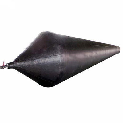
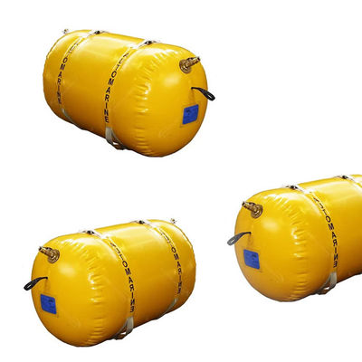
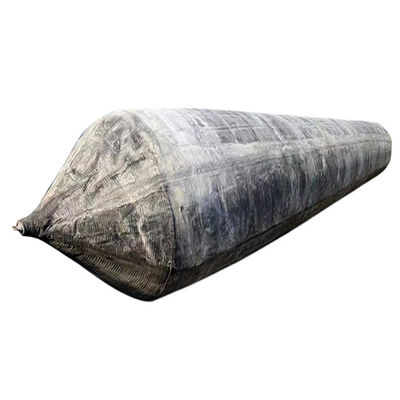
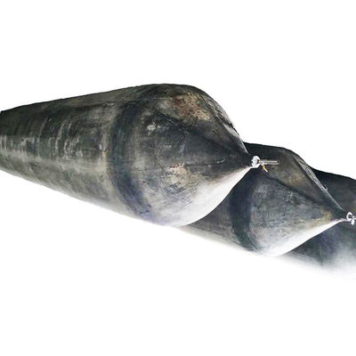
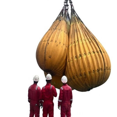
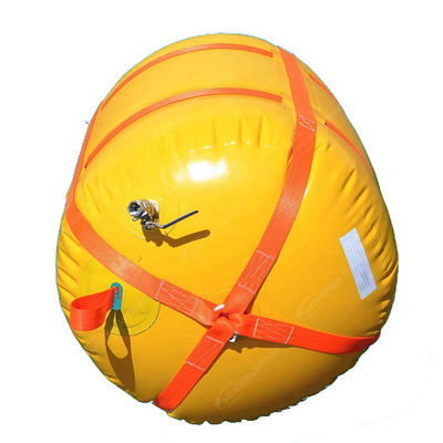
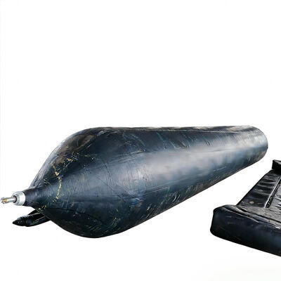
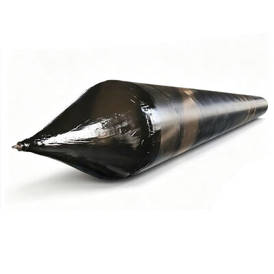
Marine Rubber Airbags are reinforced pneumatic support systems engineered for ship launching, vessel landing, hull relocation, temporary support, and controlled load transfer in marine construction and shipyard environments. The product provides a flexible interface between the vessel and the supporting surface by using controlled internal air pressure to generate load-bearing capacity.
Compared with fixed steel structures, the inflatable configuration allows the support system to be deployed, repositioned, deflated, transported, and reused according to changing project requirements.
The main body is constructed as a multilayer rubber and reinforcement composite. The inner rubber layer provides an airtight pressure-retaining barrier, while high-strength synthetic tire-cord reinforcement layers provide tensile resistance and dimensional stability. The outer rubber layer protects the internal structure from abrasion, mechanical contact, moisture, and general environmental exposure.
End fittings and valves provide controlled inflation and deflation and allow the operating pressure to be managed during vessel handling.
The operating principle depends on the relationship between internal air pressure, effective contact area, and external vessel loading. When compressed air is introduced, the cylindrical body expands until the specified operating condition is reached. Once placed beneath the hull, the inflated body establishes contact with the vessel and supporting surface.
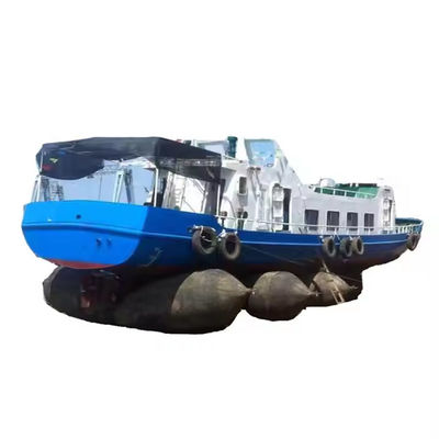
The vessel load is transferred through this contact area into the reinforced pneumatic structure. Multiple airbags can be positioned along the hull to create a distributed support arrangement and maintain progressive load transfer during movement.
A marine fabrication contractor in the United Arab Emirates needed to relocate a 2,400 ton offshore supply vessel from an assembly area to a separate outfitting and commissioning zone near the waterfront. The vessel had completed major hull fabrication, but the existing yard transportation route did not have sufficient clearance for conventional mobile lifting equipment.
Marine Rubber Airbags were selected according to the vessel weight, hull dimensions, movement route, and required support arrangement. The transportation route was surveyed and prepared, with surface projections and sharp debris removed. The airbags were positioned beneath the hull according to calculated spacing.
Inflation was performed progressively to transfer the vessel load from existing supports to the pneumatic system. Pressure readings were monitored during load-transfer, and controlled pulling equipment moved the hull at a consistent speed. Airbags were systematically repositioned to create continuous rolling support.
The vessel reached the outfitting zone without abnormal hull movement or visible damage to the airbag system, demonstrating the suitability of reusable pneumatic support equipment for vessel relocation in high-temperature coastal fabrication environments.
| Product Name | Marine Rubber Airbags |
|---|---|
| Keywords | Marine Airbag for Ship Launching |
| Material | 100% High Tensile NR |
| Dimensions | Diameter 0.5m - 3.0m, Length 3.0m - 28.0m, or as Request |
| Working Pressure | 0.05-0.25MPA |
| Technology | Overall Winding, High Pressure, Explosion Proof |
| Metal Parts | Q355 / SS304 / SS316 |
| OEM | Supported |
| MOQ | 1 |
| Repair Tools | Electric Heating Plate, Repair Materials, Glue, Free of Charge |
| Standard | ISO14409:2011 |
| Certificate | ABS, BV, KR, LR, GL, NK, RINA, DNV, RMRS |
| Package | Pallets, Wooden Cases |
| Service Life | 20 Years |
| Warranty | 36 Months |
| Diameter | Working Pressure | Working Height | Bearing Capacity KN/m | Bearing Capacity Ton/m |
|---|---|---|---|---|
| D=1.0m | 0.14Mpa | 0.6m | 87.96 | 8.98 |
| D=1.0m | 0.14Mpa | 0.5m | 109.96 | 11.22 |
| D=1.0m | 0.14Mpa | 0.4m | 131.95 | 13.46 |
| D=1.2m | 0.12Mpa | 0.7m | 94.25 | 9.62 |
| D=1.2m | 0.12Mpa | 0.6m | 113.10 | 11.54 |
| D=1.2m | 0.12Mpa | 0.5m | 131.95 | 13.46 |
| D=1.2m | 0.12Mpa | 0.4m | 150.80 | 15.39 |
| D=1.5m | 0.10Mpa | 0.9m | 94.25 | 9.62 |
| D=1.5m | 0.10Mpa | 0.8m | 109.96 | 11.22 |
| D=1.5m | 0.10Mpa | 0.7m | 125.66 | 12.82 |
| D=1.5m | 0.10Mpa | 0.6m | 141.37 | 14.43 |
| D=1.5m | 0.10Mpa | 0.5m | 157.08 | 16.03 |
| D=1.8m | 0.09Mpa | 1.1m | 98.96 | 10.10 |
| D=1.8m | 0.09Mpa | 1.0m | 113.10 | 11.54 |
| D=1.8m | 0.09Mpa | 0.9m | 127.33 | 12.98 |
| D=1.8m | 0.09Mpa | 0.8m | 141.37 | 14.43 |
| D=1.8m | 0.09Mpa | 0.7m | 155.51 | 15.87 |
| D=1.8m | 0.09Mpa | 0.6m | 169.65 | 17.31 |
| D=2.0m | 0.08Mpa | 1.2m | 100.53 | 10.26 |
| D=2.0m | 0.08Mpa | 1.1m | 113.10 | 11.54 |
| D=2.0m | 0.08Mpa | 1.0m | 125.66 | 12.82 |
| D=2.0m | 0.08Mpa | 0.9m | 138.23 | 14.11 |
| D=2.0m | 0.08Mpa | 0.8m | 150.80 | 15.39 |
| D=2.0m | 0.08Mpa | 0.7m | 163.36 | 16.67 |
| D=2.0m | 0.08Mpa | 0.6m | 175.93 | 17.95 |
Marine Rubber Airbags use a multilayer reinforced rubber structure engineered to withstand the combined effects of internal pneumatic pressure and external vessel loading. The synthetic tire-cord reinforcement is embedded within the rubber body and functions as the primary tensile component.
The structural relationship between rubber and reinforcement is maintained through controlled bonding and curing processes, creating a composite body capable of maintaining its general geometry while accommodating the deformation necessary for load transfer.
The cylindrical geometry provides a relatively long contact interface between the hull and the supporting surface. When several airbags are installed at calculated intervals, the vessel weight is distributed through multiple support locations, reducing reliance on isolated lifting points.
The engineering value of distributed contact is particularly relevant during ship launching and relocation, allowing the support system to continuously follow the vessel rather than remaining fixed in one location.
Marine Rubber Airbags may be deployed in environments ranging from exposed coastal shipyards to enclosed fabrication areas and temporary marine construction sites. The rubber compound is engineered to retain the necessary flexibility and mechanical properties under appropriate operating conditions.
The outer layer provides a protective barrier against routine abrasion and environmental contact, while the internal reinforcement remains enclosed within the composite structure for stable performance across a range of marine working conditions.
Vessel launching and relocation can require multiple cycles of inflation, load transfer, rolling, deflation, repositioning, and reinflation. The airbag structure is designed to tolerate repeated mechanical and pressure changes.
For shipyards and marine contractors, repeated usability provides an important engineering advantage because equipment can support multiple projects rather than being dedicated to a single installation.
Hongruntong Marine has more than 30 years of manufacturing experience in marine rubber products and related ship-handling equipment. This experience includes specialized process control for reinforcement positioning, rubber bonding, curing processes, and end-fitting integration into pressure-bearing structures.
Airbag diameter, effective length, reinforcement arrangement, working pressure, overall dimensions, and end fittings can be configured according to specific project requirements for cargo vessels, offshore vessels, barges, fishing vessels, and other marine structures.
Manufacturing inspections cover key production stages and finished-product conditions, including dimensional consistency, visual integrity, pressure-related inspection, and fitting checks to support stable product characteristics and reduce manufacturing-related performance variation.
Comprehensive technical information supports customers during project preparation, including product dimensions, operating pressure, installation considerations, handling methods, inspection requirements, maintenance procedures, and storage conditions.
The airbags should be stored in a dry, clean, and ventilated location away from sharp objects, excessive heat, chemicals, and prolonged direct sunlight. They should be fully deflated and properly positioned to avoid unnecessary folding stress or mechanical damage during long-term storage.
Ground condition directly influences contact stability and external surface wear. The working route should provide adequate load-bearing capacity and should be free of sharp stones, exposed reinforcement, metal edges, and other objects capable of puncturing or cutting the rubber.
Yes. They can be incorporated into horizontal vessel relocation procedures when the load, support arrangement, surface condition, and movement equipment are appropriately engineered. During movement, airbags are progressively repositioned to maintain support beneath the vessel.
Operators should monitor pressure readings and inspect the airbag surface, valves, and fittings for abnormal pressure loss or visible damage. A pressure reduction that cannot be explained by normal operating conditions should be treated as a potential leakage and investigated before continuing the operation.
Available documentation depends on project specification and applicable requirements. Product documentation may include technical specifications, material information, inspection records, pressure test records, and other quality documents. Specific certification requirements should be stated before production.