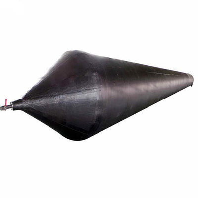
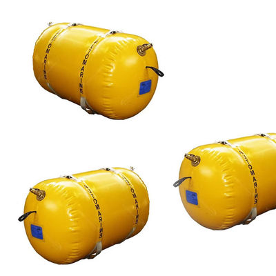
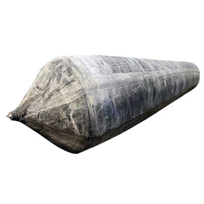
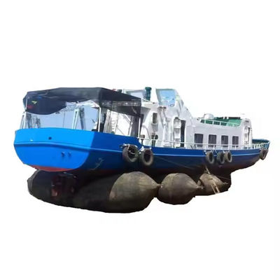
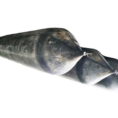
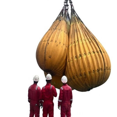
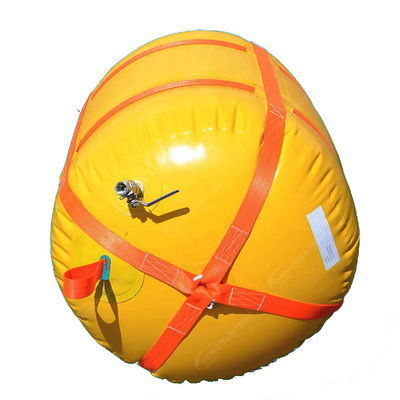
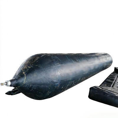
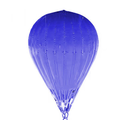
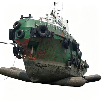
Inflatable Marine Airbags are flexible, high-strength marine handling equipment designed for controlled vessel launching, hauling, landing, shifting, and temporary support operations. The system uses a reinforced rubber body combined with multiple layers of high-strength synthetic tire cord to form a pressure-bearing cylindrical structure capable of supporting substantial vessel loads while maintaining flexibility during movement.
Unlike rigid launching infrastructure, the airbags create a temporary load-transfer interface between the vessel hull and the prepared ground or launching surface, allowing the vessel to be moved through a controlled rolling process. This engineering solution is particularly suitable for shipyards, marine construction sites, repair facilities, and coastal fabrication areas where permanent slipways or heavy lifting infrastructure are unavailable or impractical.
A marine repair contractor in Southeast Asia successfully relocated a 4,200-ton steel work vessel from an inland construction area to a coastal launching position using our Inflatable Marine Airbags. The project demonstrated the system's capability to handle large-scale vessel movement without permanent dry dock infrastructure.
Key project elements included proper load calculation, route preparation, airbag positioning, pressure control, and continuous operational monitoring. The controlled rolling process allowed completion of the relocation while establishing a repeatable operating procedure for future vessel movement activities at the facility.
| Item | Description |
|---|---|
| Product Name | Inflatable Marine Airbags |
| Material | 100% Grade A Natural Rubber |
| Type | Inflatable, Lifting, Roller, Launching |
| Diameter | 0.5m-3.0m, or As Request |
| Length | 1.0m-28.0m, or As Request |
| Working Pressure | 0.05-0.25 mpa |
| Standard | Conducted by ISO14409 and GB/T1590-2006 system |
| Accessories | Q355/SS304/SS316, Pressure Gauge, Tee, Plug, Switch, Inflation Tube |
| Packaging | Inner-Plastic Bag; Outer -Standard Wooden Pallets |
| Color | Black |
| Certificates | ABS, BV, KR, LR, GL, NK, RINA, DNV, RMRS |
| Applications | Ship launching and docking, Marine salvaging, Dry-docking, Bridge construction, Heavy machinery transportation |
| OEM | Welcome |
| Diameter | Working Pressure | Working Height | Bearing Capacity KN/m | Bearing Capacity Ton/m |
|---|---|---|---|---|
| D=1.0m | 0.14Mpa | 0.6m | 87.96 | 8.98 |
| 0.5m | 109.96 | 11.22 | ||
| 0.4m | 131.95 | 13.46 | ||
| D=1.2m | 0.12Mpa | 0.7m | 94.25 | 9.62 |
| 0.6m | 113.10 | 11.54 | ||
| 0.5m | 131.95 | 13.46 | ||
| 0.4m | 150.80 | 15.39 | ||
| D=1.5m | 0.10Mpa | 0.9m | 94.25 | 9.62 |
| 0.8m | 109.96 | 11.22 | ||
| 0.7m | 125.66 | 12.82 | ||
| 0.6m | 141.37 | 14.43 | ||
| 0.5m | 157.08 | 16.03 | ||
| D=1.8m | 0.09Mpa | 1.1m | 98.96 | 10.10 |
| 1.0m | 113.10 | 11.54 | ||
| 0.9m | 127.33 | 12.98 | ||
| 0.8m | 141.37 | 14.43 | ||
| 0.7m | 155.51 | 15.87 | ||
| 0.6m | 169.65 | 17.31 | ||
| D=2.0m | 0.08Mpa | 1.2m | 100.53 | 10.26 |
| 1.1m | 113.10 | 11.54 | ||
| 1.0m | 125.66 | 12.82 | ||
| 0.9m | 138.23 | 14.11 | ||
| 0.8m | 150.80 | 15.39 | ||
| 0.7m | 163.36 | 16.67 | ||
| 0.6m | 175.93 | 17.95 |
The primary load-bearing structure consists of specially formulated rubber reinforced with multiple layers of high-strength synthetic tire cord. This construction enables the flexible body to operate as a pressure-supported structural element while maintaining controlled deformation under vessel weight, distributing applied loads over the effective contact area.
Pressure stability is critical for supporting capacity, with the reinforced structure designed to retain intended cylindrical form while allowing controlled flattening at contact zones. Regular pressure monitoring allows operators to identify abnormal conditions and make adjustments during vessel movement.
Engineered to provide resistance against abrasion, friction, and environmental exposure during marine handling operations. The rubber compound serves as the primary protective barrier for internal reinforcement, contributing to service continuity during repeated operations.
The flexible cylindrical body can change its cross-sectional shape under load, establishing contact with vessel bottoms and prepared ground without requiring precisely machined rigid support structures. This adaptability is useful for vessels with different hull widths, bottom geometries, and construction stages.
Extensive experience across marine applications supports practical understanding of rubber material selection, reinforcement structures, pressure-bearing products, and environmental requirements for shipyards and coastal operations.
Airbags are selected according to actual vessel and site conditions, evaluating parameters including vessel weight, hull dimensions, operating surface, movement distance, and required capacity to establish suitable configurations.
Maintained manufacturing controls covering material preparation, reinforcement assembly, component integration, forming, vulcanization, and final inspection to ensure dimensional consistency and stable product performance.
Coordinates product specifications with project requirements and provides technical information for equipment selection, installation planning, operation, inspection, and storage to support B2B customers.
The quantity should be calculated according to vessel weight, hull dimensions, airbag effective contact area, working pressure, airbag diameter, spacing, ground condition, and required safety margin. The calculation should consider the actual vessel movement process rather than only static vessel weight.
The operating route should be sufficiently level, stable, and free from sharp objects or concentrated hazards. Loose material, exposed metal, broken concrete, and large debris should be removed or corrected before inflation and loading. Ground preparation is essential for safe operation.
Yes. Inflatable Marine Airbags are designed as reusable marine equipment when operated within specified conditions. After use, they should be deflated, cleaned, visually inspected, and stored properly. Any defects should be evaluated before subsequent operations.
Selection should consider vessel weight, hull width and geometry, available operating clearance, required supporting height, ground conditions, and effective contact length needed for load distribution. Dimensions should be matched to specific vessel and operating method requirements.
Provide vessel type, weight, overall dimensions, hull dimensions, launching or hauling method, operating surface, movement distance, expected working environment, and project schedule. Additional information such as photographs, drawings, or hull-bottom details helps establish accurate technical configurations.